Defender Audio Hardware Emulator
The Motorola 68000

The 1981 arcade classic Defender has a very unique sound. This page will analyze how the sound hardware and software is engineered.
Emulator
After studying the MC6802 assembly code and retrieving the Motorola M6800 Programming Reference Manual, it was feasible to write an emulator of the Defender sound hardware.

The MC6802 is implemented in a very straightforward CPU class:
class CPU
{
    // flags
    static const unsigned char C = 0x01;
    static const unsigned char I = 0x10;
    ...

    // registers
    BYTE a, b, cc;
    WORD x, pc, sp;

    // memory (ROM and RAM)
    BYTE *mem;

    // clock cycles elapsed
    uint64_t cycles = 0;

   ...
};
There is a step method that gets the opcode from the Program Counter (PC) and has a giant switch that implements the different instructions based on their opcodes:
// Get memory value at 'addr'
BYTE get8(WORD addr)
{
    SDL_assert(addr < 0x10000);
    ...
    return mem[addr];
}
bool step()
{
    // get opcode from PC address
    unsigned char op = get8(pc);

    ...

    switch (op)
    {
    case 0x01:                     ++pc; c(2); break; // nop
    case 0x07: b = lda(cc);        ++pc; c(2); break; // tab
    case 0x08: x = inx(x);         ++pc; c(4); break; // inx
    case 0x09: x = dex(x);         ++pc; c(4); break; // dex
    case 0x0e: set_flag(I, false); ++pc; c(2); break; // cli
    case 0x0c: set_flag(C, false); ++pc; c(2); break; // clc
    case 0x0f: set_flag(I, true);  ++pc; c(2); break; // sei
    case 0x10: a = sub(a, b);      ++pc; c(2); break; // sba
    case 0x16: b = lda(a);         ++pc; c(2); break; // tab
    case 0x17: a = lda(b);         ++pc; c(2); break; // tba
    case 0x1b: a = add(a, b);      ++pc; c(2); break; // aba

    ...

    }
}
The simplest instruction is NOP, which does nothing and takes two CPU cycles to execute. We just increment PC to get the next instruction and increment the CPU cycle count with 2:
bool step()
{
    ...
    switch(op)
    {
    case 0x01:
	++pc;  // next instruction
	c(2);  // increment CPU cycles
	break; // nop
    ...
    }
}

void c(int dcycle)
{
    cycles += dcycle;
}
The LDA instruction loads a value into the accumulator (register A). The implementation is trivial, save for updating the Z and N flags, indicating whether the value is 0 or negative:
BYTE lda(BYTE m)
{
    set_flag(Z, m == 0);   // update zero flag
    set_flag(N, m & 0x80); // update negative flag
    return m;              // we don't actually do anything except return the value
}
void set_flag(unsigned char flag, bool value)
{
    cc &= ~flag;           // set flag = 0
    if (value) cc |= flag; // set flag bit if value is true
}
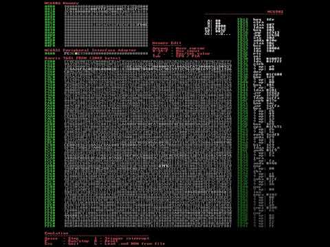
Original Defender ROM emulation test